This guide shows how to replace the flow meter of your Decent Espresso machine. This is only for machines earlier than v1.4.
Proceed as follows:
Tools:
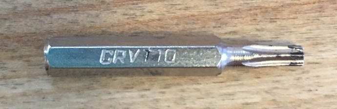
Driver with Torx T10 bit
Driver with 5.5mm (7/32”) socket wrench
Wire cutter
Small flat blade screw driver
Catch tray
Bowl for fasteners
Parts:
New Flow Meter
New cable tie, if desired
Step 1: Remove water
Run the “Transport” function from the “Machine” page on the app, in order to remove as much water from lines as possible.
Step 2: Power down the machine and let it cool
Exit the app, power down the tablet, and power down the machine with the switch on the back.
Always allow machine to cool before performing any maintenance.
Tip: before doing any mechanical work on your DE, please note that it has many small fasteners which one can potentially drop and lose, so it is helpful to put the DE in a catch tray, lined with either a towel or some rubber/plastic drawer liner. A “half” size sheet baking pan (pictured below w/tools) 13”W x 17 3/4”L (33mm W x 45mm L) is the most common home use size, and fits the DE perfectly. If you have access to a “full” sheet size, 17 3/4”W x 26”L (45mm W x 66mm L), even better as it will provide a little bigger catch area.
Step 3: Remove external components
Remove the
portafilter,
drip tray,
and water tank
and place at a safe distance where they will not be damaged by a dropped tool.
Step 4: Remove the cover
Remove the outer cover using a driver with a Torx T10 bit installed.
There are (4) black M3x8mm screws on either side of the machine.
Place in a bowl until time to reinstall.
Turn the machine so that you have access to the “pump side” which is the right side of viewing from the barista's perspective. The flow meter is located above the pumps.
Step 5: Remove the flow meter wiring connector
Remove the flow meter wiring connector, located on top of the flow meter, by slowly and gently pulling up and wiggling side to side a bit if necessary.
Carefully place connector and wiring out of the work area, preferably folded over to the other side of the machine.
Step 6: Remove the flow meter outflow hose and intake line
Carefully remove the flow meter outflow hose which is the top hose on the flow meter, leading to pumps.
Use a small flat bladed screw drive, if necessary, to help work the hose off the flanged barb, taking care not to tear of nick the hose.
In like fashion, remove the flow meter intake line, which is the bottom hose on flow meter, leading to intake assembly at back of machine.
Position both hoses out of the work area.
Step 7: Remove the holding nuts
Remove the (2) nylon locking nuts that hold the flow meter mounting bracket against the “bulkhead”, which is the central partition of the chassis, via (2) threaded posts,
The nuts are located just under the flow meter, using a hand driver fitted with a 5.5mm socket wrench.
As half size metric sockets are not common here in the US, I used a 7/32” socket, which fits snuggly and presents no risk of damaging the mating faces of the nut.
To access the rearward nut you may need to fold the cold water pump intake line out of the way a bit, as in the video.
Step 8: Remove the flow meter with its bracket
Carefully remove the flow meter and bracket by gently pulling on the bottom of the bracket, so that the holes in the plate slide over over the mounting posts on the bulkhead wall,
then guide the whole assembly between the steam wand supply line and the top of the pumps.
Step 9: Remove the flow meter from the bracket
Remove the flow meter from the mounting bracket by first clipping the cable tie (if any) securing the flow meter to the aluminum mounting bracket with a wire cutter,
then pulling the flow meter out of the two post holes on the bracket.
Step 10: Install the new flow meter
Install the new flow meter with intake and outflow barbs positioned the same way they were oriented on the old flow meter (so they will the back of the machine when the assembly is reinstalled).
If you desire, you may install a cable tie as with the old flow meter. As you can see in the video, I did not.
Step 11: Position the new flow meter
Carefully work the new flow meter and bracket assembly between the pumps and steam wand supply line, working the top of the assembly through first,
then sliding the bracket holes over the threaded posts mounts on the bulkhead.
Step 12: Replace the nuts
Replace the (2) 5.5mm nylon locking nuts, using the socket driver to make them snug.
Step 13: Replace the flow meter intake and outflow hoses
Replace the flow meter intake hose, fitting it to the bottom barb on the flow meter, being sure that the hose is sufficiently seated over the sealing flange.
Replace the flow meter outflow hose, fitting it to the top barb on the flow meter, taking care to route the out flow hose between the bulkhead and the intake line, so that it does not interfere with the water intake assembly lifting mechanism.
Again be sure that the hose is sufficiently seated on the sealing flanges.
Step 14: Replace the flow meter wire connector
Step 15: Replace the machine cover
Step 16: Replace the external components
Replace the water tank, drip tray, and portafilter
Questions?
If you have any questions or run into any difficulties, don't hesitate to reach out to our online tech support.
#repair #DIY #howto #documentation